How to set-up a Castel Xellip2
How to set-up Xellip 2 Panel
TABLE OF CONTENTS
- Set-Up Guide UK Basic Standalone Mode (peer to peer)
- Configuration
- Request to Exit
- Maintenance
- Functions
- Configuring Relations
- Self-Test Function
- Technical Characteristics
Set-Up Guide UK Basic Standalone Mode (peer to peer)
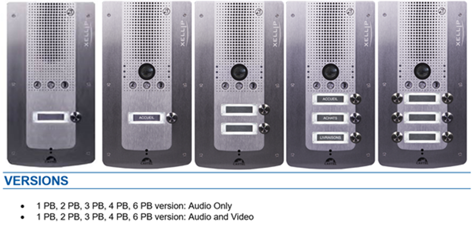
The door entry station is part of a comprehensive, powerful full IP multimedia system. It features native SIP and the following functions (version-dependent):
- Set up Audio/Video over IP communication
- Recording on SIP server (option of configuring up to two backup servers)
- Management of 1 to 6 programmable call buttons
- Management of two digital inputs
- Management of two dry contacts to control a strike plate, or any other equipment item
- Compliant with the ‘disability law’: 3 LEDs associated with 3 pictograms and 3 voice syntheses used to signal the call, set up the call and activate the strike plate
- Integrated induction loop
- PoE (Power Over Ethernet), PoE+ (Power Over Ethernet Plus)
- Management of two Ethernet 10/100/1000MB ports, bridge function (used to connect another IP system) or independent interface
- Backup on power outage
- Management of station profiles according to time slots
- Management of advanced automated control systems (logical relations and times) on its interfaces
- Self tests (automatically or on request)
- Integration of RTSP (Real Time Streaming Protocol)
- Integration of SNMP (Simple Network Management Protocol)
- Compatible with ONVIF (Open Network Video Interface Forum)
- ASCII notification management
- VLAN support
- Protection of Ethernet connections via protocol 802.1X (RADIUS)
- With its embedded Web server, it can be configured, monitored and used from any browser
Connections:
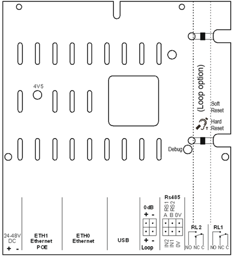
Power supply connection (24-48 VDC)
Required power supply is 24 Vdc to 48 Vdc.
Note: the door entry station can be powered by the Ethernet network by using PoE or PoE+.
IP network connection (ETH0/ETH1)
The connection uses a 10/100/1000 Mbps Ethernet RJ45 link.
2 Ethernet ports available (1 compatible with PoE or PoE+ and 1 non PoE)
Relay output connection (RL1/RL2)
The connection uses a 3-pin terminal supplying the ‘Common (C)/Idle (NC)/Operating (NO)’ interface.
If you use one of these relay outputs to control an AC or DC strike plate, wire a non-polarised 58 V diode in parallel on the dry contact between C and NO or C and NC depending on use (diode included).
Input connection (IN1/IN2/0V)
Two digital inputs enable the connection of a dry contact (do not apply voltage). To be activated, the input must be pulled to ground.
The contact can be remote (up to 1 km).
0 dB output connection (0 dB)
A 0 dB output enables a connection to an external amplifier
Audio induction loop output connection (Loop)
A Loop output connects the audio induction loop.
Possibility of connecting the loop ref.: 590.9040 for better range.
Protection against electrostatic discharge
Connect the door entry station by using the terminal supplied (mounted on microphone mount).
Configuration:
Station IP address
Each station must have its own IP address on the network. This address will be either given by the network server (DHCP addressing), that is manually configured. This addressing can be configured from a PC via the station's Web server.
Note that the station is delivered by default with DCHP. If no DCHP server is present, the station will then use a fixed IP address of the IP4All domain: 169.254.xx.xx
The station's IP address can be found from:
- CastelIPSearch application
- ONVIF discovery software
If the station's IP address cannot be found:
- In factory settings mode, when pressing the 1stprogrammable button, the station announces its IP address
- When the ‘Soft Reset’ push button is pressed briefly, the station announces its IP address
- When the ‘Soft Reset’ push button is pressed for more than 3 seconds, the station bridges its IP interfaces with a fixed IP of 192.168.49.251.
Station reset
When the ‘Soft Reset’ push button is pressed for more than 20 seconds, the station restarts and resets its parameters to the factory settings.
When pressing the ‘Hard Reset’ button, the station restarts instantly.
Access to the station Web Server
To log into the station Web server, simply use a web browser such as Firefox, Chrome or Internet Explorer. You do this by opening your Web browser from any PC on the network and typing: ‘https://’ followed by the IP address of the entry station ([https://entry_station_ip_address]). You will then be directly connected to the entry station's Web page. You only have to type in your login (by default: admin) and your password (by default: admin) to access the Web server functions.
Note: for compatibility with Edge, the blocking of pop-ups must be disabled. To do this, go to ‘Parameters’, ‘Advanced parameters’ then disable ‘Block pop-ups’.
Once logged in you will see this screen

It is important you click on Switch this will change all the tones and WAV file to the English Version
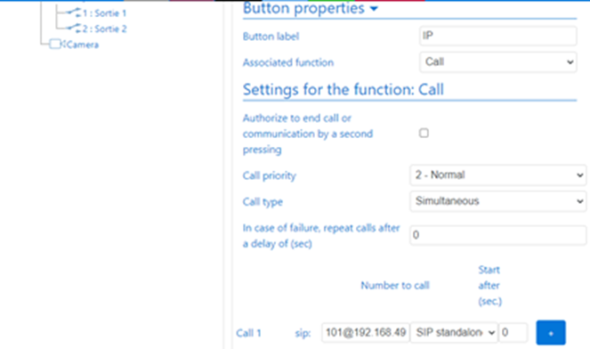
From the Left Hand tree menu click on Button this is designated to what the Panel needs to Call.
In this case I have set it to call 101@192.168.49.101 this is a standalone designation
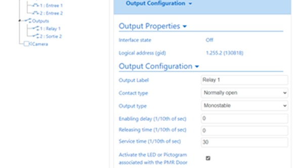
Click on the Sortie 1 these are just the onboard relays and label as Relay 1 and Relay 2 respectively. The service time is how long you want the relay to operate for.
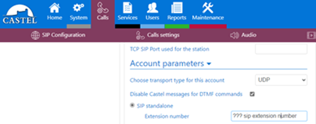
Click on Call and Sip Configuration and enter a SIP extension number this used to make up the standalone SIP Number and the Server Extension number if it is connected to a SIP Server.
For the Lock Release Action we need to create a relationship between a DTMF tone and an Action.
Generally DTMF1 is used for Lock Release

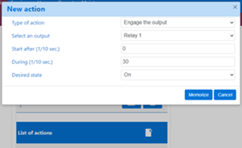
Title the Action as Lock Release, Click on List of Actions Scroll down and find Engage the Output, Select the Relay (or sortie if not changed) you wish to activate, set the duration to your required release time and then click Memorize
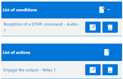
This will then recap what you are trying to achieve and if correct click on Save

The Panel is now set-up to make a Call to a unit SIP Number 101@192.168.49.101 on answer they then can release door the by pressing DTMF1. Which will release the door for 3 seconds.
Please note the Panel will need to set in the 192.168.49.xxx range.
Request to Exit:
If a Request to Exit is required, please follow this process:
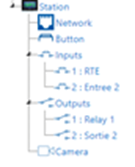
Relabel the Input you are going to use for Request To Exit
Click on SYSTEM then Relations this will list all the Relations already set.

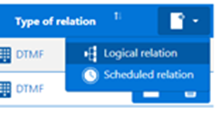
Click on + and select Logical Relation
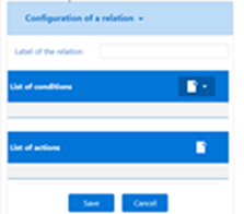
Name the Relation for Example Request To Exit and select List Of conditions and select Input RTE Click Memorize.
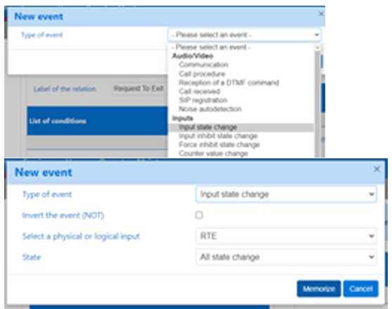
You now need to select the action this input will cause.
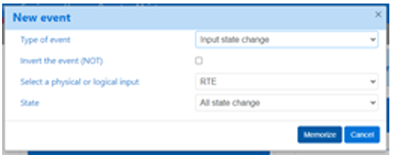
The Type of Action will be Engage The Output and then select the Relay that is controlling the Lock and then click Memorize
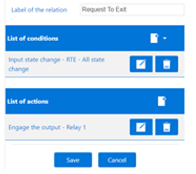
Review your setting in this case when the input to RTE is seen then it will activate Relay 1, if this is correct select Save.
If wrong click Cancel and start again.

This will now be added to your list of Relations
Maintenance:
Your CASTEL product must only be cleaned using a mild cleaning product (water or soapy water) that is non-abrasive, non-foaming and above all free from any type of solvent or alcohol.
For regular maintenance, only use water, without detergent.
Jet cleaning is prohibited, as well as use of abrasive sponges and cloths with aggressive surfaces.
Functions:
The entry station is designed to interface, via the IP network, with all the other stations of the Intercom over IP range (XELLIP, CAP IP, etc.), with a Softphone, a SIP telephone, or any other element compatible with the SIP standard.
General functions of the entry station
- Configuring a network connection.
- Configuring an SIP account
- Setting the date and time manually or via an NTP server
- Management of audio and video communications (according to version)
- Setting a level of priority for the device
- Setting a call and communication timeout
- Automatic answering with and without delay
- Activating privacy mode for automatic answering
Audio interface functions
- Configuring the volume of the speakers, microphone and audio induction loop
- Configuring the Anti Echo Acoustic (AEC)
- Configuring the RTP port number
- Enabling/Disabling audio codecs
- Configuring ring tones and tones
- Configuring DTMF commands used to control the local relay, for example
- Configuring noise detection used to activate a call, for example
- Switching to simplex through a DTMF command from the calling party station
- '*' switches to listening simplex
- '#' switches to speech simplex
- '0' is used to return to standard operation
Video interface functions
- Configuring the video source (Local/RTSP)
- Activating/Deactivating video encoding
- Resolution selection (QCIF/QVGA/CIF/VGA/HD)
- Activating bandwidth management
- Configuring the RTP port number
- Enabling/Disabling video codecs
Programmable button functions
Each button can be programmed and is used to:
- Call 1 to 10 stations simultaneously or with timeout
- Control the local relay, the relay of the station on a call
- Send a DTMF code
- End a call
Digital input interface functions
- STATUS or COUNTER input configuration
- Input active status configuration (open or closed contact)
- Recognition timeout configuration for a status change (debouncing function)
- Counter threshold configuration
- Input inhibition
Output interface functions
- Relay output type configuration: monostable, bistable or flashing
- Normally Open/Normally Closed contact configuration
- On/Off output control
- Open/Closed override output control
- Output time parameter configuration
Logical input functions (or flags)
The logical inputs enable two functionalities in particular:
- Creation of a logical status from which actions can be conditioned in relationships.
- Creation of a counter that will be updated according to events and depending on the value of this counter, possibly trigger one or more actions.
Configuring Relations:
The web server is where automatic controls, also called relations, are configured
There are two types of relations:
- Time: used to trigger actions at identified time slots. There are three levels of priority for a time relation (high, medium and low).
- Logical:
- Logical condition: used to trigger actions at certain status conditions (active, inactive, etc.). A logical relation can integrate several conditions by operators such as AND, OR, NOT, XOR. Likewise, a logical relation can trigger several actions.
- Digital condition (Counting): used to perform actions by comparing the value of a counter with different thresholds. It is also possible to add or subtract counter values and compare the result obtained.
Configuration of web server users (software users)
The Web server for the station can grant, modify or remove rights for users by specifying their login, password and operating language.
Profile configuration
Station operating profiles can be created, modified or deleted. Each profile specifies a station priority, a configuration of function buttons and access rights to the station.
The station can operate with a unique profile or with different profiles according to time slots.
SNMP administration management
The station features an SNMP agent (Simple Network Management Protocol) that can respond to SNMP queries and send notifications (TRAPS) to an SNMP manager.
From web pages, it is possible to:
- Configure different communities (read/write)
- Configure system data (sysContact and sysLocation)
- Configure notifications (recipient, community, etc.)
- Download MIB Castel
It supports the SNMPv1 and SNMPv2c versions.
Self-Test Function:
The station has several tests to validate its operation:
- HP/MIC self-test: can remotely test the right operation of the speaker and microphone. From the ‘advanced parameters’ page, the levels of this test can be adapted according to the installation environment. This test can be activated from the web server or by an SNMP command. The result of the test can be viewed from the web server history and by an SNMP notification.
- Mechanical button self-test: the detection of a locked mechanical button (contact made for more than 20 s) is signalled by an SNMP notification and an event is signalled in the web server history.
Backup and Recovery of System Parameters:
A full backup or recovery of the station parameters can be made (configuration, profiles, relations, directory, etc.
The door entry station can be reset to factory settings by pressing the reset button for 10 seconds when the station is started up.
Station update
For the update, you will be provided with a file containing the new software version, if necessary.
You must then download this file via the Web Page. The entry station will restart so as to apply the update. The update does not modify the user parameters in any way.
Backup on power outage
When a power outage occurs, the station can back up the following information:
- counter values
- history
- backed up events (these events are defined from CastelServer)
- The interface statuses
History function
The history displays station events. They are listed by showing the date and time of the relevant event, a description and additional information.
Functions used to meet the accessibility law (depending on versions)
Rule: 'Any signal related to the operation of an access device is audible and visual.'
During the call, the entry station sends a configurable voice message and the call signal LED switches on.
When the call is set up, the entry station sends a configurable voice message and the call signal LED of the entry station switches on.
During the internal relay command at the station, the entry station sends a configurable voice message and the door signal LED of the entry station switches on.
Rule: 'When there is an electrical unlocking device, it enables any person with reduced mobility to reach the door and start the opening manoeuvre before the door becomes locked again'
The entry station’s strike plate relay can be configured with a configurable hold time.
Rule: 'In the absence of a direct view of these accesses by staff, the intercom devices feature a system enabling staff to view the visitor
The entry stations have a wide angle colour camera.
Rule: 'When they are installed or renewed, the intercom devices have a magnetic induction loop
Entry stations have an integrated magnetic loop.
Technical Characteristics:
Compliance with European standards
- Safety rules according to standard
- IEC/EN 60950-1.
- EMC emission according to standard
- EN 61000-6-3
- EN 55022 class B
- EMC immunity according to standard
- EN 61000-6-1, EN 61000-4-2 (8 kV),
- EN 61000-4-3 (3V/m),
- EN 61000-4-4 (2kV).
- EN 55024
Mechanical characteristics
- Tamper-proof design
- Degree of protection
AUDIO: IP65 as per EN 60529
VIDEO: IP65 as per EN 60529
- 316L stainless steel front panel
- Flush ABS base with wall mounting
- Door entry station dimensions: H 280mm x W 145 mm x D 63 mm
- Weight: 1.4kg
General electric characteristics
- Protection against electric shock class 3 as per EN 60950.
- Operating temperature: -20°/+50°C.
- Storage temperature -20°/+70°C.
- Relative humidity: <90%, without condensation.
- Power supply: 24 VDC (24 V to 48 V).
- Power consumption: 24 Watt max
Buttons
-
Acquisition speed 5 Hz (200 ms)
Inputs
- 2 protected and filtered digital inputs
- Acquisition speed 5 Hz (200 ms)
Outputs
- potential-free relay outputs
- Relay cutoff power 42.4 Vac/60 V dc/5 A/150 VA
- The maximum frequency is 5 Hz (minimum switching time: 200 ms)
Camera
- Sensor CMOS 1/4’’ 1280x800
- 170° wide angle
- Low brightness vision: 5 Lux minimum at 80 cm
Audio codecs
- G711 Ulaw/Alaw
- GSM
- G722
- G729
Video codecs
- QCIF/QVGA/CIF/VGA/HD video format
- H263
- H263-1998
- H264
- VP8
- MP4V-ES
DTMF
- RFC-2833
- SIP INFO
Ethernet 10/100/1000 Mbps network
- Fixed IP or DHCP
- PoE class0 conformity with standard IEEE 802.3af
- PoE+ conformity with standard IEEE 802.3at
- Security of Ethernet connections via protocol 802.1X
- SNMP V1 and V2c
- Upstream bandwidth in audio/video communication: 2 Mbps
- Ports used: 22 (ssh), 443 (https), 5060 (sip), 10800-10801(audio), 10802-10803(video).
- Additional ports that can be used by the station according to the services used: 123 (ntp), 161-162 (snmp), 554 (rtsp), 3702
Please download the attached PDF
Please use our FTP Site for Firmware and documentation on all our products
Username = UDPC05\FTP1
Password = #V2RK$Z@q\
Please use Internet Explorer as many browsers are blocking access to FTP sites
Navigate to Castel Folder for all the latest documents and firmware
