How to fix getting no call to the video monitor for the K-Steel and Sinthesi Entry Panels
Use this article to fix the issue of not getting a call to the video monitor for K-Steel and Sinthesi Entry Panels.
This article is relevant for the K-Steel and Sinthesi entry panel modules 1755/41, 1755/81, 1745/41 and 1745/81, and is intended for single entrance, single call button systems with no call to the video monitor.
Notes:
- Start by checking that the call has not been muted at the monitor. Different monitor models have different methods to mute the call.
- Check the instructions for that particular model.
- If the monitor does not ring it is also likely that you will not have a picture (the screen will not light up).
- If you don't have a picture and the monitor does not ring, follow this article first.
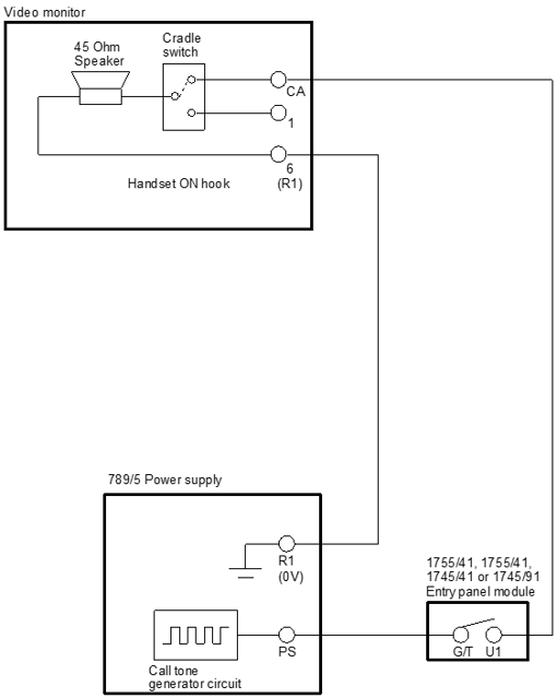
With reference to the diagram below, disconnect U1 and G/T in the entry panel module. These are the contacts either side of the push button, so they should normally be open circuit and when you press the call button they should go closed circuit.

- Check that across U/1 and G/T there is an open circuit that goes closed when the button is pressed. If there is a permanent short circuit or if the contact does not go closed when the button is pressed, the module should be replaced. If the button contact is operating correctly re-connect G/T and U1.
- The call tone is a DC voltage that measures 19V and originates from a circuit inside the 789/5 power supply. Measure between R1 and PS on the 789/5 power supply. There should be about 19V DC. If not then disconnect PS and re-measure. If you now have 19V then the fault is likely to be in the cable between the power supply and the entry panel.
- If you still do not have 19V DC on the PS terminal then it is likely that the 789/5 needs replacing. If you have 19V on the PS terminal of the 789/5 then measure between R1 and G/T of the entry panel module. If you do not have 19V then the fault is in the cable between the power supply and the entry panel.
- If you do have 19V DC between R1 and G/T of the entry panel module, measure between R1 and U1 of the entry panel module. You should have 0V. Next press the call button and you should now have around 5V DC (The 19V has been loaded by the monitor). If you do have around 5V DC between R1 and G/T of the entry panel module when the button is pressed then it is likely that the monitor/bracket is faulty.If you don't have around 5V then disconnect U1 and re-test.
- If you now have 19V (U1 is disconnected and so there is no load) between R1 and U1 when the button is pressed, then the fault is either the cable between the entry panel and the monitor/connection bracket or the monitor/connection bracket.
- Reconnect U1. Go to the monitor and disconnect CA. Measure between R1 of the monitor/bracket and the end of the wire that was in CA. When the button in the entry panel is pressed (two people required for this test) you should measure 19V DC. If you don't then the fault is in the cable between the entry panel and the monitor/bracket. If you do then it is likely that the monitor/bracket needs replacing.
