Controllers are designed to be wall mounted through 4 screws but can also be DIN rail mounted.
A cover is supplied.
Wiring Diagram - PSU & Readers:
The controllers communicate through BLE with the mobile phone.
NOTE: The USB plug is only used by the factory.
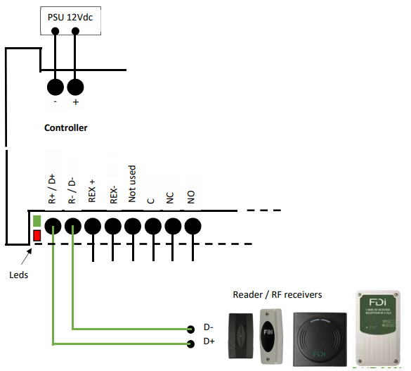
NOTE: the green led is ON while the relay is activated. The red led flashes once every 3 secs when the reader is working fine and is flashing 3 times/sec if the reader is not connected or not answering to the controller.
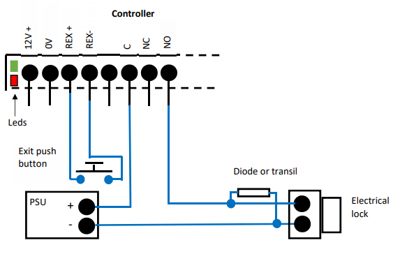
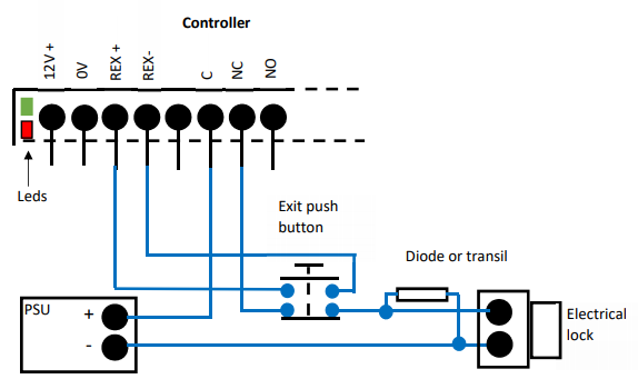
Wiring Diagram - Lock
When a fail-safe lock is used, a second security must be used to prevent an issue between the REX push button and the controller.
Basically, a break glass is connected in serial with the lock psu or the push button manages two dry contacts : 1 NO contact for the controller REX input + 1 NC contact in serial with the lock or maglock psu. (see wiring diagram above).
When a fail secure lock is used, the REX push button is NO as shown below.
Fail Secure Lock
Fail Safe Lock/Maglocks
Test the Controller